Applications of induction Motors in Industry
 The induction motor can be viewed as as an AC transformer with a rotating secondary winding.
When an ongoing flows in stator windings a current is caused when you look at the shorted secondary windings by transformer action. The magnitude associated with rotor present should be proportional into flux thickness B floating around gap (and the general movement, called the, regarding the rotor with regards to the rotating field once we shall see below).
Torque is from the response between your induced rotor currents and the air-gap flux produced by the stator currents.
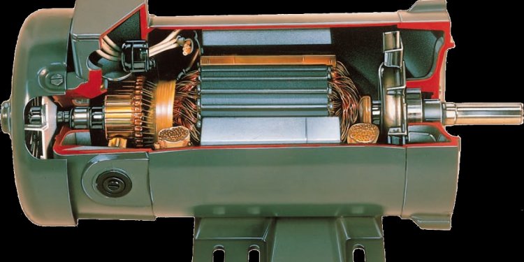
Many rotor kinds are used. The preferred AC engines use "squirrel cage" rotors that are constructed from copper or aluminum bars fixed between performing end bands which offer the short-circuit course for the currents caused inside taverns.
Since there are no connections on rotating windings, the costly commutator are eliminated with it, a potential supply of unreliability.
As soon as current is flowing inside rotor windings, the engine action because of the Lorentz force from the conductors makes effect. The response between your existing flowing when you look at the rotor conductors additionally the magnetized flux floating around space causes the rotor to rotate in the same course since the rotating flux as if it had been being dragged along by the flux wave.
Just like the DC machine, the torque in an induction motor T is proportional to your flux density B together with caused rotor current I. hence
T = k1 BI
In which k1 is a continuing with respect to the wide range of stator turns, how many levels and also the setup associated with magnetic circuit.
The rotor speed accumulates as a result of the engine action explained above, but as it does therefore, the relative movement amongst the rotating stator area in addition to rotating rotor conductors is paid off. This in turn reduces the generator action and so current into the rotor conductors while the torque on the rotor. Given that rate of rotor approaches the rate for the rotating area, referred to as, the torque in the rotor falls to zero. Thus the rate of an induction engine cannot reach the synchronous speed.
An induction motor is therefore an asynchronous device
S = Ns- Nr
Ns
Where S may be the slip, Nsis the synchronous speed in RPM, and Nr could be the rotor rate.
Since the rotor current is proportional on general motion involving the rotating area and also the rotor speed, the rotor existing and therefore the torque tend to be both directly proportional to the slide.
The rotor present is proportional into rotor resistance. Increasing the rotor resistance will certainly reduce the present and increase the slide; for this reason a kind of rate and torque control can be done with . Increased rotor resistance also has the additional good thing about decreasing the feedback rise current and increasing starting torque on switch on, but each one of these advantages are at the expense of more complex rotor styles and unreliable slip rings to provide access to the rotor windings.
Ns = 120 ()
p
Where is the powerline regularity in Hz and p could be the amount of poles per phase. p must certanly be an even integer since for each north pole there is certainly a corresponding south pole.
Listed here table shows motors rates for engines with various numbers of poles using different AC supply frequencies.
Rotor Speed (rpm) |
|
Amount of poles |
10 |
12 |
||||
|
Frequency 50 Hz |
3000 |
1500 |
1000 |
750 |
600 |
500 |
|
Frequency 60 Hz |
3600 |
1800 |
1200 |
900 |
720 |
The specific speed associated with the motor will depend on force it should drive. Enhancing the load regarding engine triggers it to delay enhancing the slide. The motor speed will settle at an equilibrium rate whenever motor torque equals the load torque. This takes place when the slip provides adequate existing to deliver the desired torque.
Note in addition that since the in rotor is proportional into and flux thickness consequently is proportional toward line voltage, the torque, which is determined by the product associated with the flux thickness and rotor existing, is proportional towards the square of the range current V.
If an induction engine is obligated to operate at speeds in excess of the synchronous speed, the load torque surpasses the device torque and the slide is negative, reversing the rotor induced EMF and rotor present. In this situation the device will behave as a generator with energy becoming gone back to the offer.
In the event that AC offer current to the stator excitation is actually eliminated, no generation is achievable because there is no induced existing when you look at the rotor.
AC engines are microprocessor managed to an excellent level and certainly will regenerate current down to nearly an end whereas DC regeneration fades quickly at reasonable speeds.
Three phase induction engines and some synchronous motors aren't self-starting but design improvements including auxiliary or "damper" windings regarding the rotor are integrated to overcome this issue.


